The diagram below illustrates the main components of your MAX X.
Hood
Build platform knob
Build platform
Build tray clamps
Basin
Touch screen
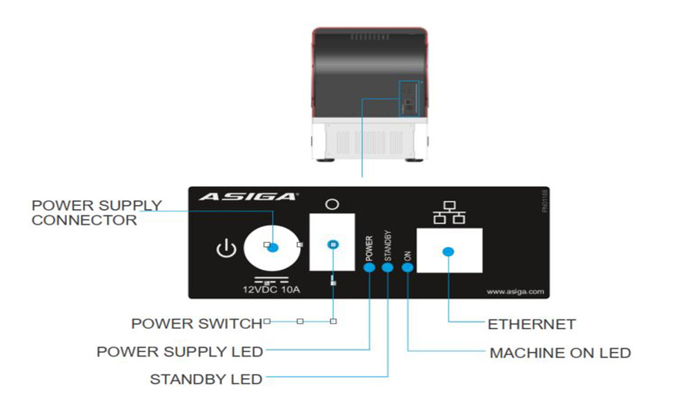
Connecting to power
The MAX X is supplied with an external power supply and a power lead with a plug type suited to your region. The external power supply automatically regulates to adapt to the local voltage in your region.
The power supply is safe to use from 100V to 240V.
Place the printer on a sturdy surface.
Connect the power cable to the printer and a power outlet.
Flip the Power Switch at the rear of the printer & turn the printer on with the power button on top.
The power button should turn green when turned on.
Language selection
When the MAX X has been plugged in and powered on, there are a few steps that need to be performed before printing.
First you must select your desired language.
Printer registration
Please create an Asiga account to access the Material library, software downloads & technical support. Learn more >
Navigate to www.asiga.com/register and insert the printer serial number displayed on screen.
Fill out the following fields & click Activate.
Serial Number
Printer Location
Enter this activation code on the front panel of your MAX.
Once the code has been succesfully entered, tap on register.
Your printer should now be fully operational.
Connecting to your MAX X
There are three ways to connect to your MAX X 3D printer:
Wired/ethernet connection
Wifi
Wireless direct
See below a summary of each of these networking methods.
Wired/Ethernet connection
From the Main Menu select Settings.
Select wired network.
If your network cable is connected properly, you should see an IP Address here.
If there is nothing visible, check the network cable on the rear of the printer or router.
Assign fixed IP address
If you wish to assign a fixed IP address to your printer, follow the steps below.
Select Settings > Wired Network
Toggle off ‘Automatic Configuration’
Enter the IP Address & select save.
Enter the Subnet Mask & select save.
Setting the Gateway, Primary DNS and Secondary DNS are optional & may be left blank.
WiFi connection
From the Main Menu select Settings.
To set up a WiFi Connection, select wireless network.
Select Network Name and find your network from the dropdown list.
Note: Wireless Direct must be turned off!
Wireless direct
Wireless Direct allows the printer to act as a wireless access point. This can be used if there is no router available.
From the Main Menu select Settings.
Select Wireless Direct
Note: This will prevent any WiFi connections to be performed.
Default settings for Wireless Direct:
Wireless Network: Printer name
IP address: 172.27.10.1
Subnet Mask: 255.255.255.0
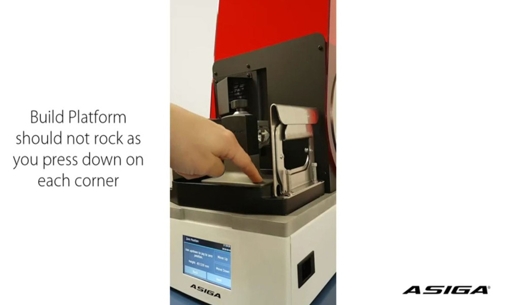
Build platform calibration
Build Platform Calibration must be performed regularly to ensure optimal performance from your printer.
Play Video
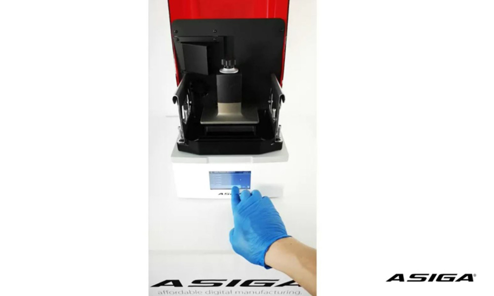
Build platform validation
To finalise the build platform calibration, follow the below video.
Play Video
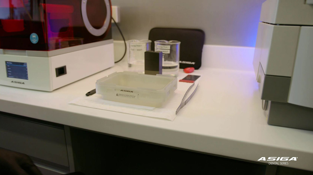
Inserting build tray & resin
The final step to getting your printer print ready!
Eye or skin contact with uncured resin may cause irritation.