Build Trays
FAQ
Introduction
UltraGLOSS™ by Asiga allows you to 3D print clear parts directly with a glossy / pre-polished surface removing the need for manual post-polishing.
No special post processing steps are required.
This page will explain how to process parts correctly using the UltraGLOSS build tray to achieve optimal results.
3rd party materials
UltraGLOSS™ is compatible with 3rd party materials listed in our Open Material Library.
For any biocompatible material it is important that you follow the post-processing guidelines identified in the material manufacturers IFU.
If you have questions regarding post-processing 3rd party materials then please contact the material manufacturer directly.
Suggested applications
- Dental
- Night Guards
- Occlusal Splints
- Audiology
- Earshells, Earmoulds
- Earmould shells for casting silicone
- General
- Clear applications where a gloss surface finish is required. Packaging, visors etc
Printer compatibility
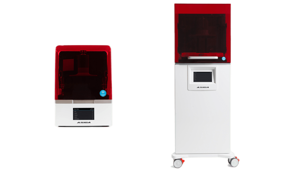
- MAX, MAX X – 1L only
- PRO 4K , PRO 4K XL – 2L only
Orientation
This section covers how to orient a nightguard/splint correctly to reduce support contact points.
Reducing support points or eliminating them will reduce finishing time providing an optimal outcome when using the UltraGLOSS build tray.
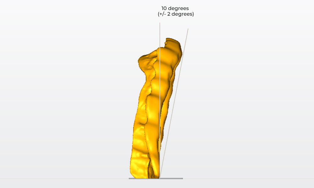
For optimal and consistent print results, it is essential to orientate the nightguard / splint in the following way:
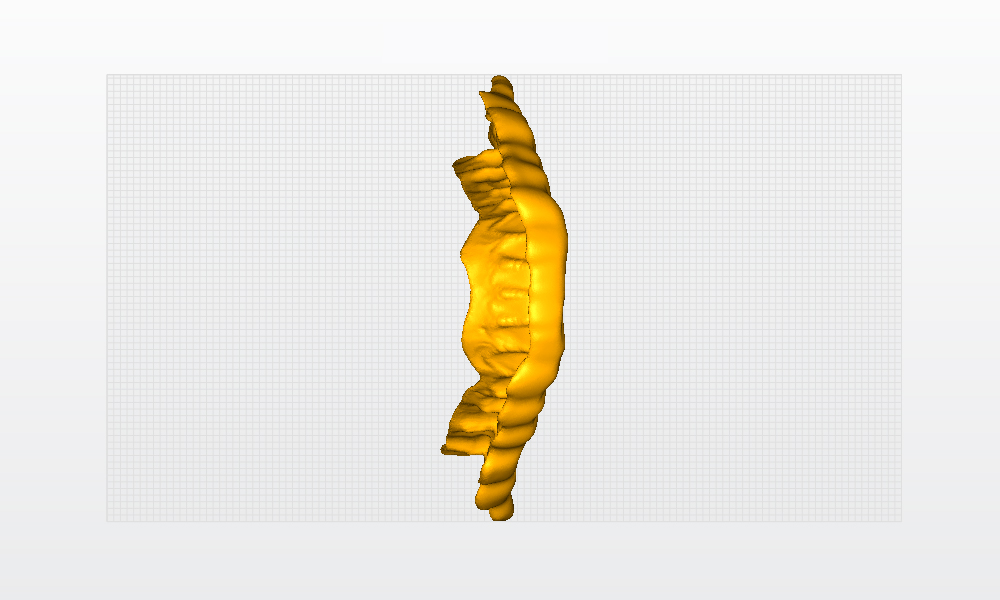
- Position the nightguard / splint vertically, ensuring that only the distal ends of the appliance contact the build platform.
- Once established, angle the splint 10 degrees from the vertical with the occlusal surface facing up.
- The distal ends of the appliance will require supports. Support structures across the arch may not be required.
We recommend checking for islands using the clipping tool in Composer.
Supports
Removing or reducing support points will reduce finishing time and provide a more optimal result.
This can be managed in four ways:
- CAD Design Option 1 – planar cut
- CAD Design Option 2 – custom supporting structure
- Composer Option 1 – print below platform
- Composer Option 2 – add sprues / supports
CAD Design Option 1 - planar cut
Introduce flats on the distal ends of the appliance.
Orient the appliance at the angle specified in the Orientation section and make a single planar cut through both ends of the arch.
When the appliance is then positioned from this cut surface coincident on the build platform, the appliance should stand at the correct angle.
CAD Design Option 2 - custom supporting structure
Add a custom support structure to the design prior to exporting the STL data.
This can also be done in Composer but there is greater control around the geometry of the supporting structure if designed in the CAD program.
In the example below there are sacrifical cubes placed at both ends of the device.
When post-processing the appliance it is important to minimize handling of the glossy surfaces.
Sprues or supports can help with the post-processing as they provide a detail that can be handled.
These support structures will need to be removed as the final post-processing step.
Refer to case study by Matthias Zimmerer here >
Composer Option 1 - print below platform
By moving the appliance below the platform surface or outside of the buildable area, you can mimic the adjustment made in CAD Design Option 1.
Orient the appliance at the angle specified in the Orientation section and position the appliance on the platform surface.
Select the part & use the transform panel to move the device to -2mm or -3mm in Z.
The transform panel can be found in the bottom left corner of Composer.
To unhide the transform panel, navigate to “View > Transform Panel”.
Important note: The geometry that sits outside of the printable area will not be printed so consideration must be made regarding whether this has an impact on the fit of the appliance.
Composer Option 2 - add sprues/supports
Orient the appliance at the angle specified in the Orientation section.
Then open the Generate Support dialog.
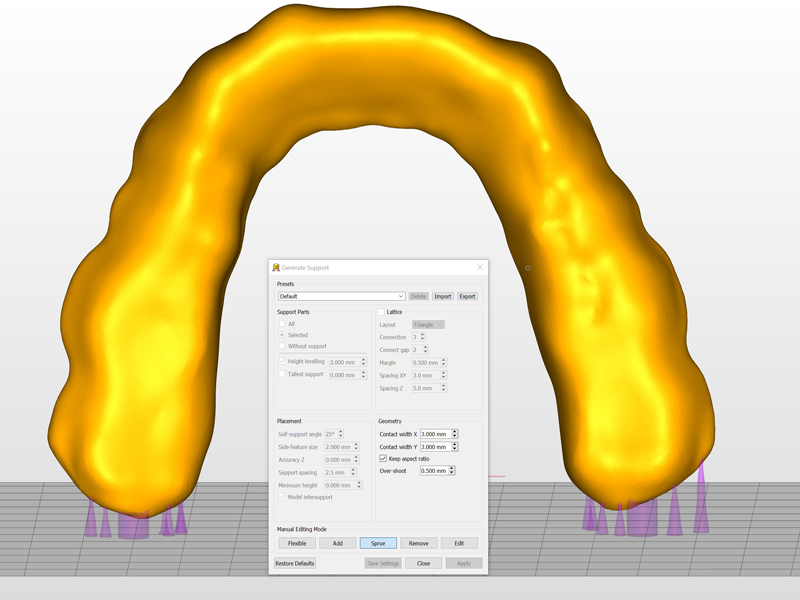
When post-processing the appliance, it is important to reduce handling of the glossy surfaces.
Sprues or supports can help with the post-processing as they provide a detail that can be handled.
These support structures will need to be removed as the final post-processing step.
Setting up UltraGLOSS™ in Composer
You will need to be running the latest version of Composer.
You can download the latest version of Composer in your Asiga account online here >.
There are some important actions to be taken in Composer when setting up the build.
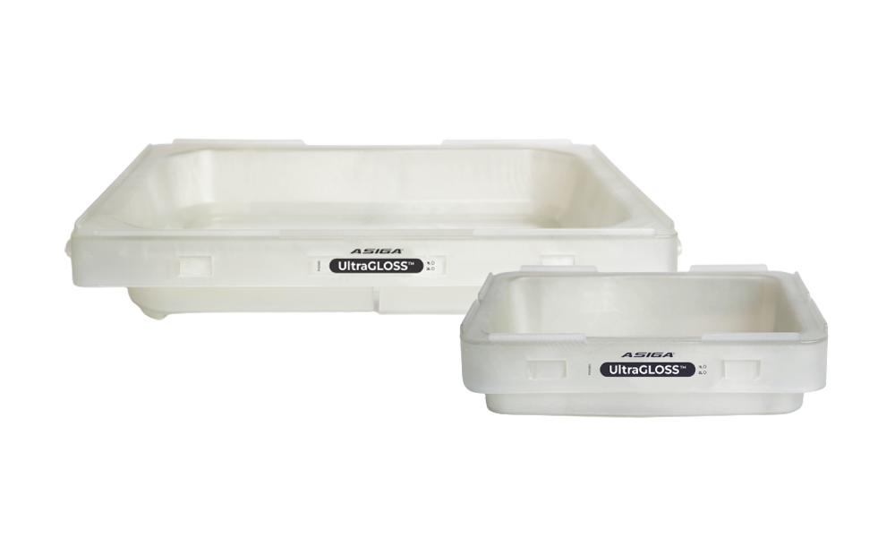
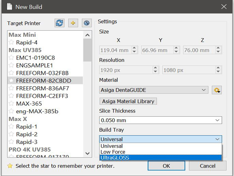
1. Ensure the correct Build Tray is selected
In the build dialogue, select UltraGLOSS from the Build Tray drop down list.
There are three types of build trays available for Asiga printers. To learn more about each one, see here >
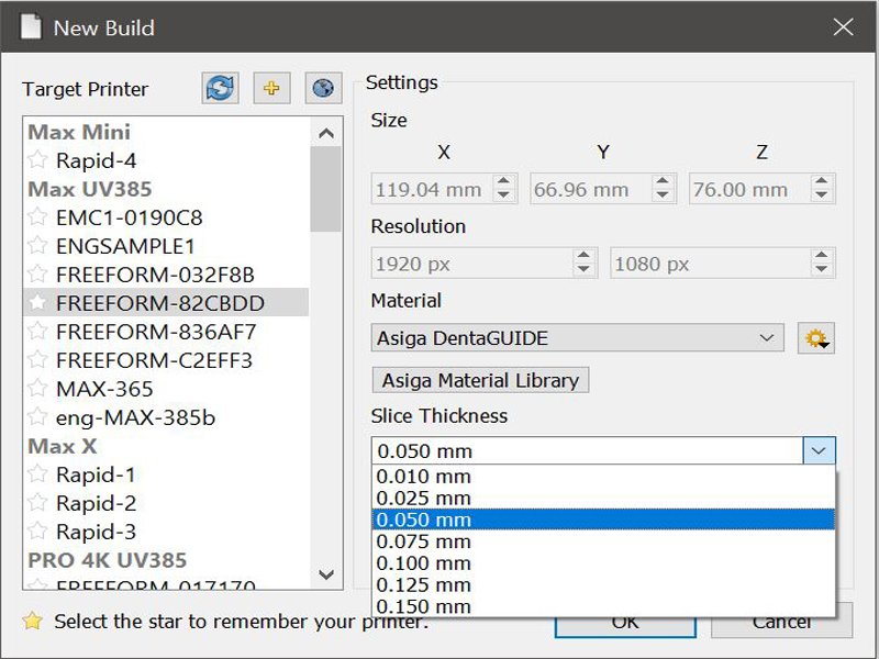
2. Input the recommended layer thickness
The optimal layer thickness is 0.05mm (50 micron).
50 micron layers will provide the best & clearest surface finish.
You can still achieve a glossy finish when printing with thicker layers, but the layering will be more visible.
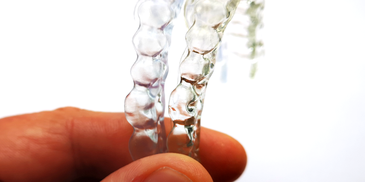
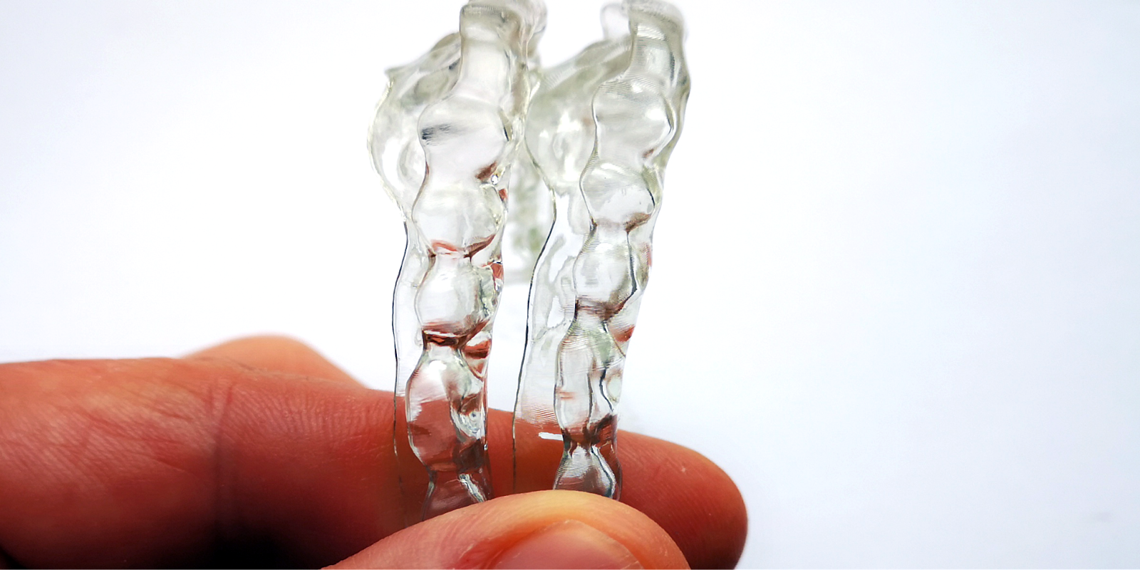
Here is a comparison image:
- Left: Printed at 50 micron layers
- Right: Printed at 100 micron layers
Setting up UltraGLOSS™ on your printer
1. Insert UltraGLOSS Build Tray into printer
Ensure the Build Tray is free from debris.
If this is a used build tray and you are unsure whether there are any debris present then we recommend you clean the tray.
Instructions on how to do this can be found here >

2. Add material to the fill level marker
Washing
Post processing the parts after printing is a crucial step to ensure the surface of the appliance remains glossy.
Follow the post-processing instructions as outlined in the material manufacturers IFU. Follow these steps carefully and also take note of the following handling advice:
1. Washing - handle the appliance carefully
Try to minimise contact with the appliance.
Handle the appliance by the sprues / supports if available or take care when touching the surface of the appliance during washing as the surface is delicate until fully cured.
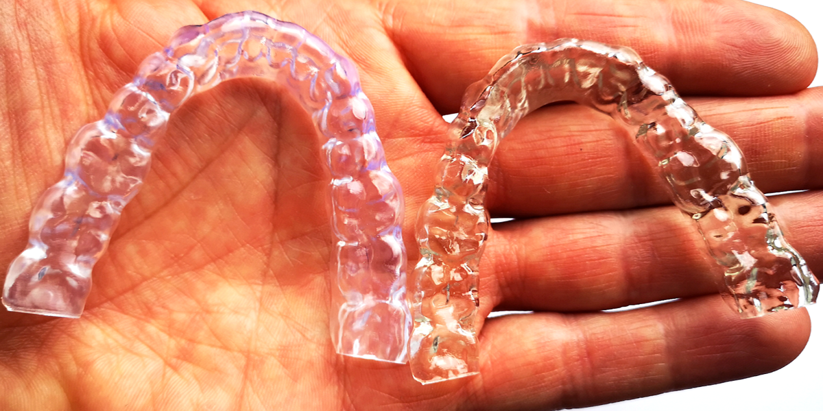
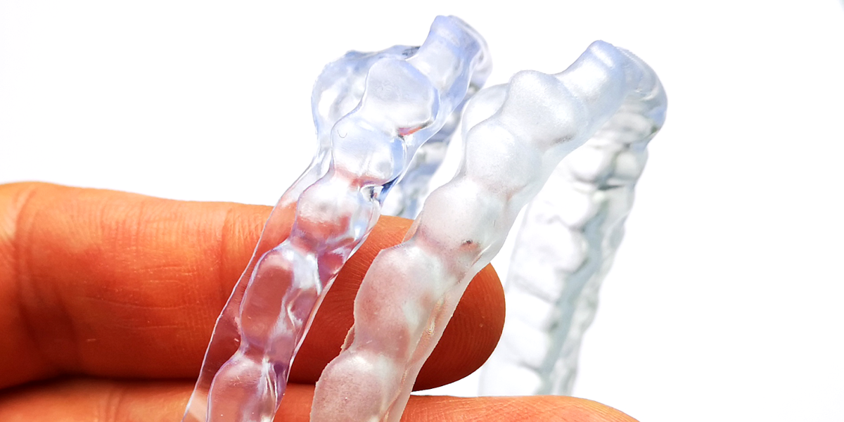
Below is a comparison showing two different outcomes after post-processed.
Left – an appliance handled carefully
Right – an appliance that has been rubbed on the surface during washing
UltraGLOSS™ with different materials
Different materials have different chemistries and post-processing outcomes.
Below you can see images of two nightguard/ splint materials being used with UltraGLOSS.