Below is a summary of the main components of the MAX X.
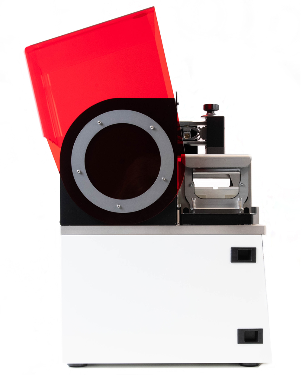
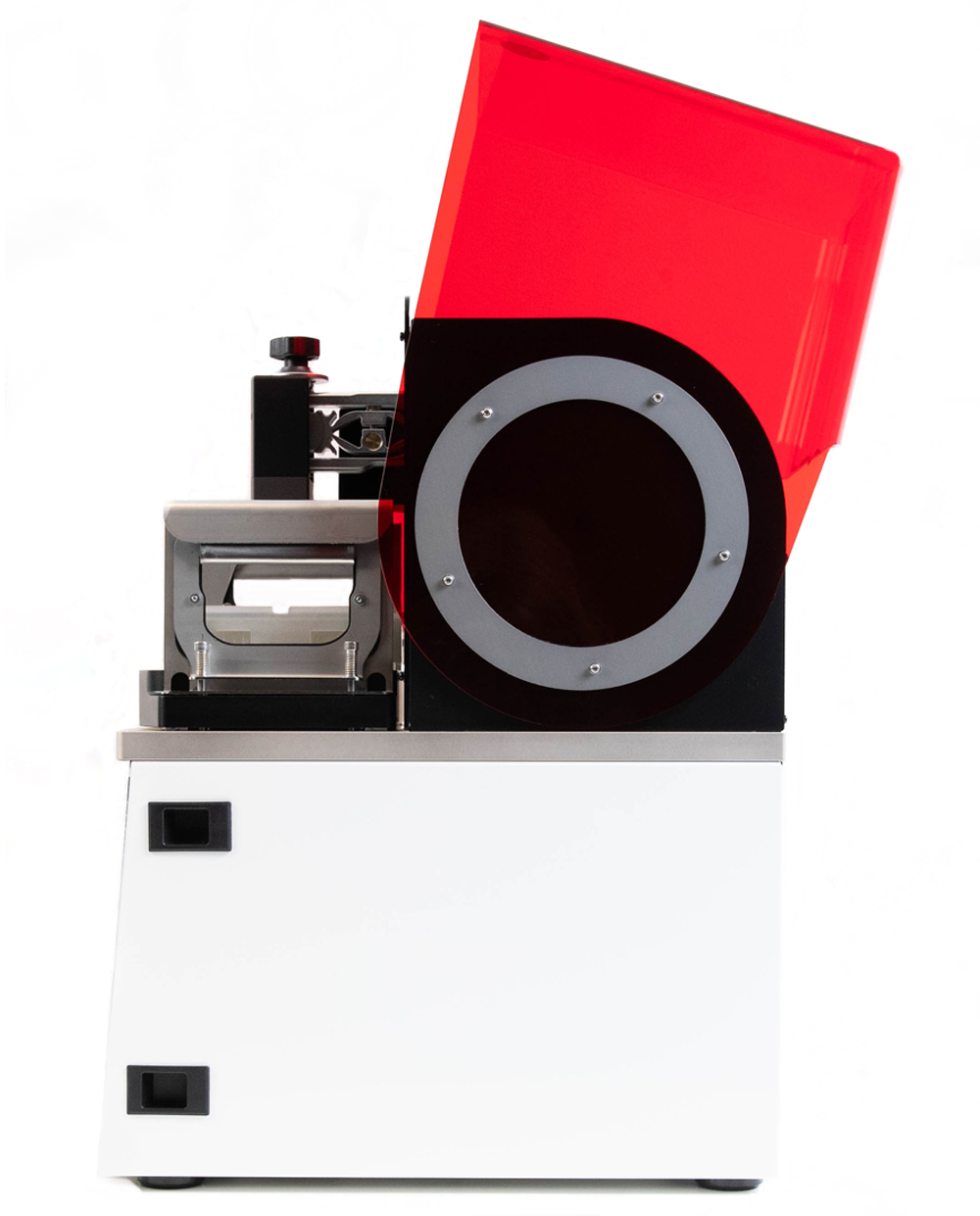
Hood
The MAX X Hood is constructed of UV blocking hard plastic. This protects the resin from being cured by natural light & the user from UV light emitted.
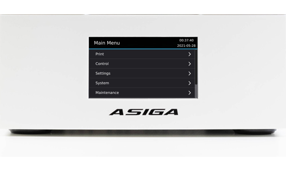
Front panel
The front panel is the white surround that contains the LCD screen. The LCD screen controls the printer.
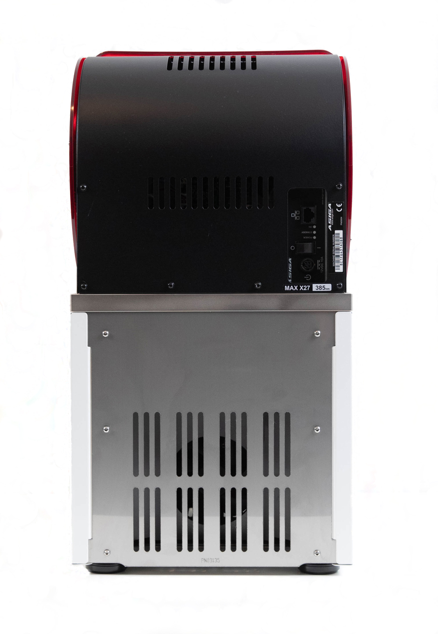
Connectivity panel
The rear panel is constructed of a curved black metal sheet with cut-outs housing the power and network plugs.
This panel can be quickly removed for service and access to all printer electronics.
The stainless steel panel on the lower half is the bottom rear cover.
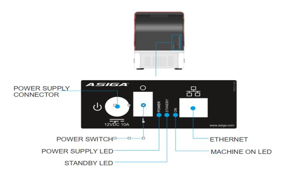
Power buttons & connectivity
On the rear of the printer is a connectivity panel. See diagram below for all inputs.
There is a power ON/OFF button on the top of the printer.
Side panels
The side panels are constructed of metal and painted white. These can be removed by disengaging the black plastic clips and hinge open.
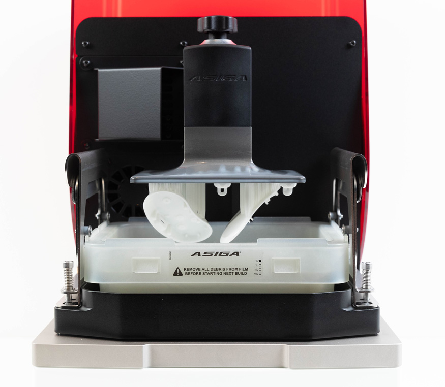
Under the hood
Build platform holder
The build platform holder is the arm that protrudes from the vertical stage.
The build platform calibration screw is located here.
Build platform
The build platform is the centerpiece of the MAX X.
It is engineered from anodised steel which makes it extremely durable.
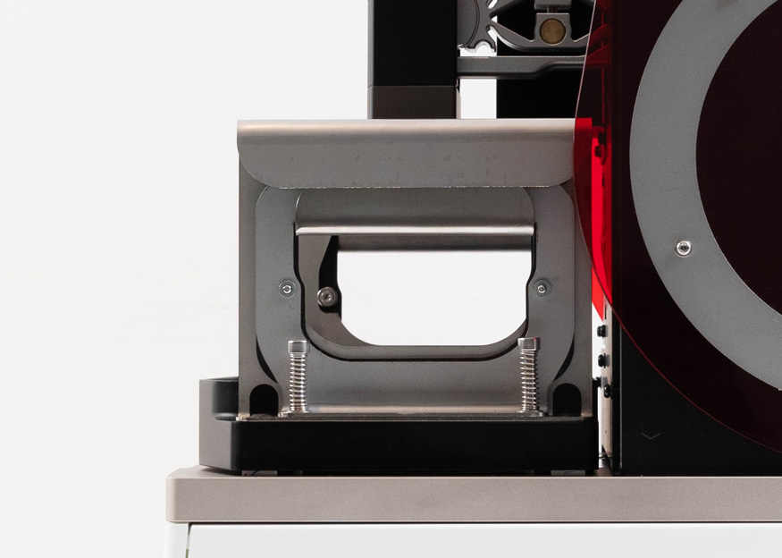
Basin
The basin holds the resin tray and acts as a gateway between the resin and UV light. This glass plate must be kept crystal clean and free from debris.
Build tray
Build trays contain the resin during the printing process. They are comprised of a flexible film that moves with the build platform.
Asiga recommends one Build Tray per material. Do not
use the same Build Tray for multiple materials as this may create material
cross-contamination and transfer of uncured materials.
Build tray clamps
The clamps are designed to hold the basin in place during the printing process.
SPS™ Positioning Encoders
Asiga SPS™ technology is managed by 4 position encoders that surround the basin glass.
These sensors detect actual build platform positioning to ensure the layers in your 3D printed part are formed accurately.